Note: This is the first draft, expected to be revised
Essential Tools
- A multimeter
Optional Tools
- Oscilloscope
- Function Generator
Types of Voltage
- AC Voltage (Alternating Current Voltage)
- DC Voltage (Direct Current Voltage)
Common Sources of Voltage
- Mains power supply (AC voltage) [from large generators using magnetism] *
- Batteries (DC voltage) [from chemical reactions] *
- Charged capacitors (DC voltage – be careful of large capacitors, they can provide enough voltage for a nasty shock) [from transfer from other voltage sources]
- Generators / Alternators (AC voltage) [from magnetism] *
- Static charge (DC voltage, normally not used in design, but necessary to protect electronics from it) [from friction, or transfer from another voltage source]
- Photovoltaic sources (DC voltage – like solar cells) [from light] *
- Piezoelectric effect (This effect is usually used to make transducers rather than voltage sources to power electronics) [from pressure on certain materials]
- Thermoelectric effect (DC voltage) [from heat]
- Antennas / Aerials (AC voltage in very small amounts) [from electromagnetic transmissions, or unwanted noise from other circuits/machines]
- Transformers, Power Supply circuits, and Inverters (These change voltage levels, and convert from AC to DC and DC to AC) *
* These are the usual direct or indirect sources of voltage to run electronics.
Measuring Voltage
You will need a Multimeter to measure voltage.
Measuring DC Voltage
Voltage is measured between two points. If there exists any voltage between these two points, one side will be on positive voltage, and other on negative voltage in comparison to each other. A multimeter has two probes, a red one for positive side of voltage, and a black for negative side of voltage.
It doesn’t matter too much for modern digital multimeters which way you connect the probes to the positive and negative points. If you put the red probe on the positive side, and black probe on the negative side, the readout on the display will be a positive number. But if you put the probes in reverse, i.e. black probe on positive side, and red probe on negative side, then the meter will just show the voltage in negative.
On older, analogue multimeters, correct direction did matter, because there was a needle which only had the scale in one direction to show the voltage, and in the wrong direction it would not have much ability to move, and could damage the multimeter.
Experiment 1: Measuring Battery Voltage
Required Items and Tools
- A 1.5V battery (AA, AAA, C, or D type)
- A multimeter
Setting up the Multimeter and taking voltage measurement
- Connect the black probe to COM socket (or input jack, or terminal)
- Connect the red probe to the socket that has V marked on it. V can be in combination with other things such as Ω, A or mA, C, and the diode symbol ⏄, depending on the type of multimeter you have.
- Turn the dial to 20V in DC Voltage section. Depending on the model, DC Voltage maybe mentioned by DCV, V⎓, only V if both AC and DC are measured in the same section. Majority of digital multimeters turn on when you rotate the dial to this setting, but some even have a separate on/off switch or button. Some have a separate switch to select AC or DC. So check your multimeter carefully, read its manual if there’s any confusion.
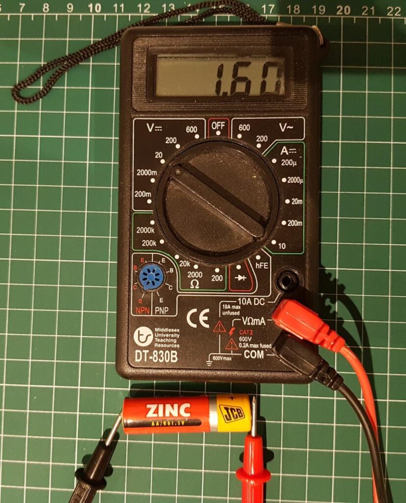
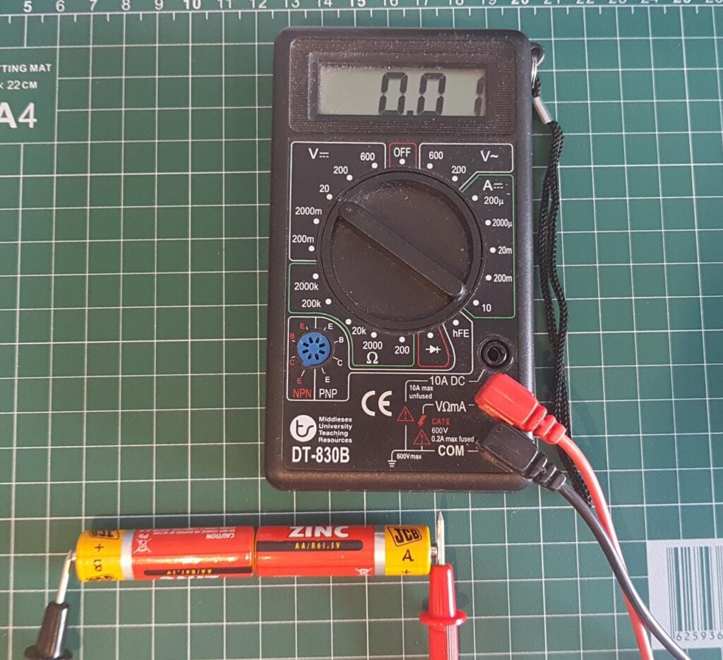
- Now connect the red probe to the positive side of the battery and the black probe to the negative side of the battery, and read the voltage shown on the multimeter display.
Now swap the probes from positive to negative side on the battery and read the voltage shown on the multimeter display (ONLY ON DIGITAL MULTIMETER, NOT ANALOGUE MULTIMETER).
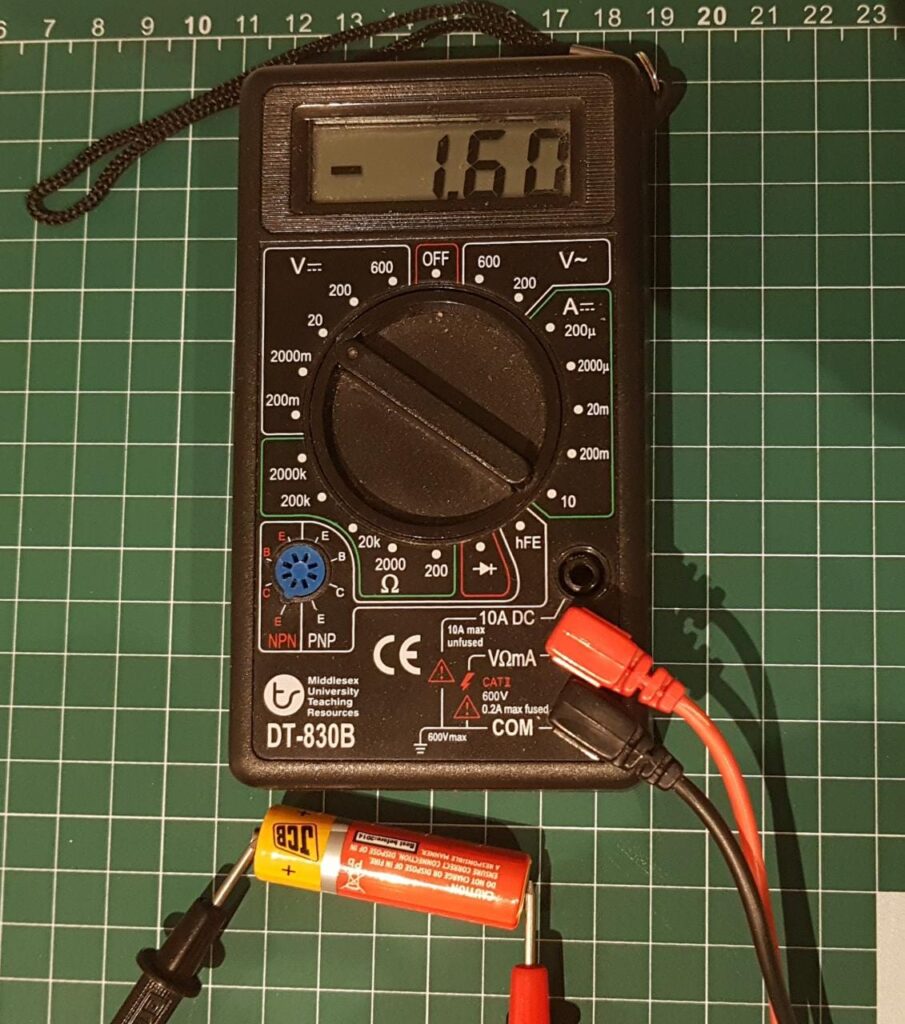
Now turn the multimeter off.
Experiment 2: Voltage Sources in Series
Required Items and Tools
- Three 1.5V batteries (AA, AAA, C, or D type)
- A Multimeter
Mark the batteries as A, B, and C for reference
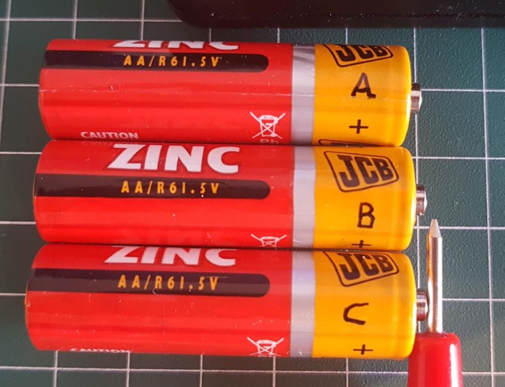
Measure and note the voltage for all three batteries. Follow the procedure explained in Experiment 1. Batteries are expected to have slightly different voltages due to inconsistencies in manufacturing processes and storage conditions if the batteries are new, or different consumption levels if they are used ones.
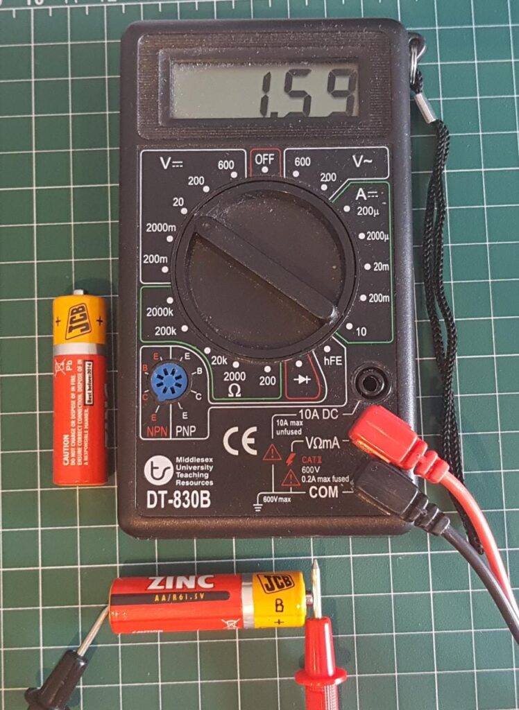
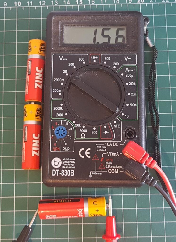
Measured voltages for my batteries came out as below:
Battery A: 1.60V
Battery B: 1.59V
Battery C: 1.56V
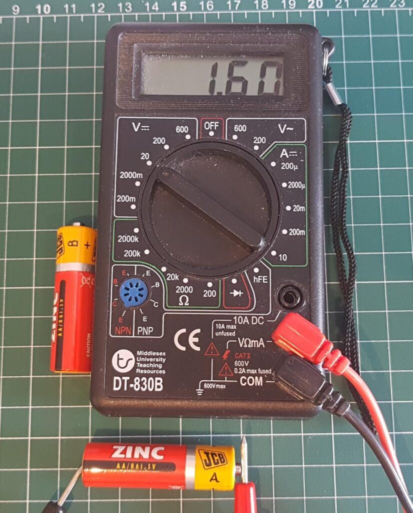
Total voltage across different voltage sources in series is equal to the algebraic sum of the individual voltages
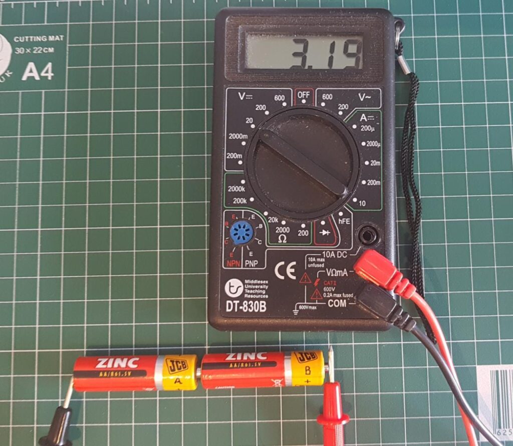
VBattery A + VBattery B = 1.6V + 1.59V = 3.19V
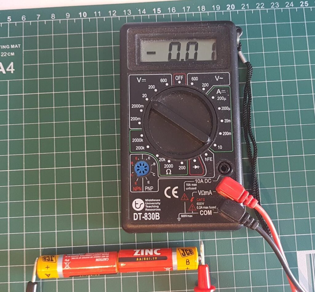
-VBattery A + VBattery B = -1.6V + 1.59V = -0.01V
-VBattery B + VBattery A = -1.59V + 1.6V = 0.01V
The above three examples are a physical verification of the validity of algebraic sums and signed numbers.
Now try VBattery A – VBattery B and VBattery B – VBattery A and see if mathematics and reality still match.
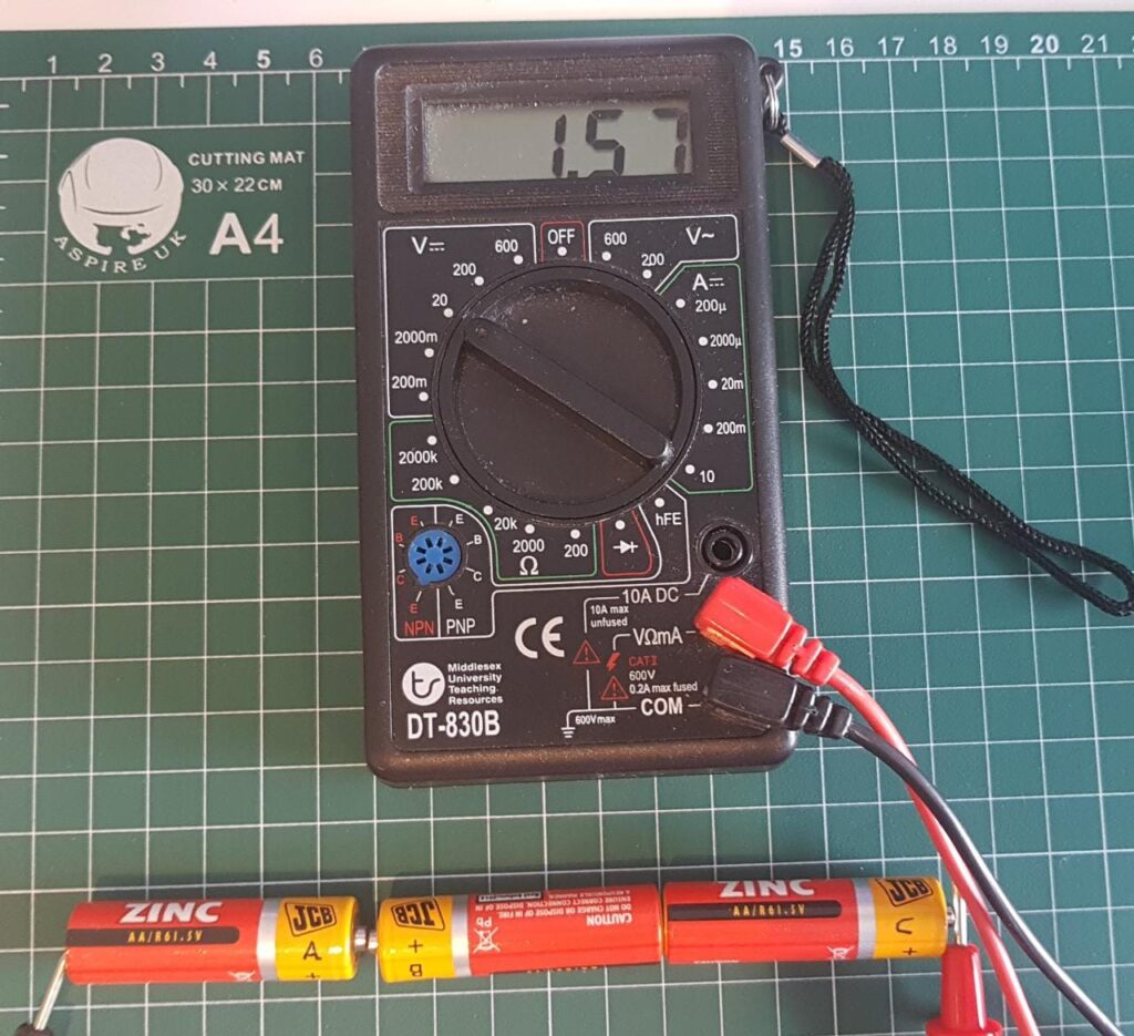
This works for more than two batteries too. Here three batteries are placed in series:
VBattery A – VBattery B + VBattery C = 1.6V – 1.59V + 1.56V = 1.57V
Mathematics, accuracy of the multimeter, and the physical reality voltages, all match up perfectly for my batteries and multimeter. Do they match up for your batteries too?
Now try the following:
VBattery A + VBattery B + VBattery C
VBattery A + VBattery B – VBattery C
-VBattery A – VBattery B – VBattery C
In practice, we don’t put batteries like this in unmatched polarities (plus and minus or positive and negative) for two reasons.
- There’s no point of using three batteries in series (1.5V – 1.5V + 1.5V) to achieve 1.5V if we can do it with just one battery.
- More importantly, batteries don’t like opposing voltage across them, they get hot, get damaged and may even explode if their polarities are mixed that way. They didn’t heat up or explode while we were measuring the voltages with the multimeter is because the multimeter doesn’t allow a lot of current to flow through its probes while measuring the voltages, which means it’s not the same as the batteries being in an electronic circuit which works by allowing current through it. More on this later.
Therefore, we do use multiple batteries to increase the voltage, by putting them all in same polarity alignment (positive of one battery to negative of other battery, but never positive to positive or negative to negative connections).
AC Voltage
You may have seen a wave shaped line showing AC voltage, and may think that it’s something that travels like a wave, but that is not the case. Alternating Current is not a wave, waves travel in one direction like waves in water. Alternating Current oscillates back and forth rather than travel anywhere in waves.
Then why do we show it as a wave? Well, the wave doesn’t show the motion of electricity (current), it is simply a graphical representation of the voltage amplitude (magnitude, amount) change in time.
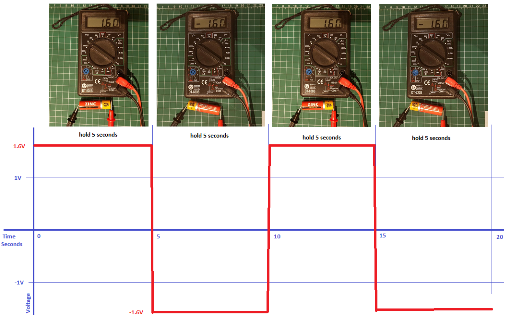
Consider this example, you hold the battery for 5 seconds in positive direction, then reverse it every 5 seconds. You alternately get 1.6V and -1.6V on the meter for 5 second durations. If you were to plot this on graph paper, where x-axis was time in seconds, and y-axis was voltage in volts, you will get the following graph, assuming that you are really fast and change the direction of the battery in a fraction of a second. What is alternating here is the polarity of the voltage, i.e. it becomes positive, and then it becomes negative, and then repeats the cycle. When you connect the battery, it immediately provides the full voltage of 1.6V. So the graph below is showing AC voltage. But you will say that these are straight lines, not a wave like the one shown for AC current! Well this is also a wave, we call it square wave. It’s the change of polarity at regular intervals that makes it AC current, not the shape of the wave.
Then why is AC voltage always shown as a curvy wave rather than like the square wave graph above? That’s because the mains AC power doesn’t come from flipping batteries; it comes from generators that produce electricity by turning inside a magnetic field. They don’t have the ability to immediately supply a high voltage in either polarity, instead they start from zero and slowly rise to the maximum voltage, and then gradually drop to zero, and then gradually decrease the voltage below zero to the negative side for same amount as it went above zero, and then gradually come back to zero, and start the cycle again. If this cycle happened in one second, it will be called 1 Hz (Hertz). If it happened 50 times a second, it will be called 50 Hz (meaning that the generator has spun exactly 50 times in a second). 50Hz is the frequency (taken from how frequently something happens, and standardised against a second). This is same as 3000 RPM (Revolutions or Rotations Per Minute). We get this 3000 RPM value because there are 60 seconds in a minute, and 50 rotations of the generator per second, so it rotates 60×50 = 3000 times in a minute. Depending on your country, you will be getting either 50Hz or 60Hz mains supply. In developed countries, great efforts are taken to maintain the specified frequency because a lot of technology is dependent on the preciseness of the frequency. In underdeveloped world, this frequency has a lot of fluctuations and may not even be precise at any time.
Measuring AC Voltage
You can measure AC Voltage with a multimeter, but it doesn’t actually measure all the parameters of AC Voltage because it’s not simple like DC Voltage. So instead, it gives us some standardised approximations of AC Voltage.
The main source of AC Voltage is the mains supply in your home, from a generator, or from an inverter that produces AC Voltage from DC sources (normally batteries). The AC Voltage would be usually 220V or 110V, depending on your country. But before we measure AC Voltage with a multimeter, let’s see how its graph looks like.
Apart from the AC sources mentioned above, we can produce AC voltage from a Function Generator, which classifies as laboratory equipment. If you have access to one, you will have to read its manual to know how to operate it, or get help from someone who knows – they have less standardised menus and settings compared to a multimeter.
We can see the graph of voltage against time being plotted on an Oscilloscope, which is another type of laboratory equipment. They too have their own menus and buttons depending on their brand and model, so if you have access to one, read the manual or seek help from someone who knows how it works.
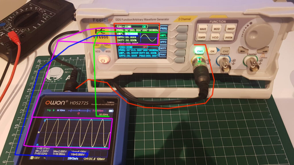
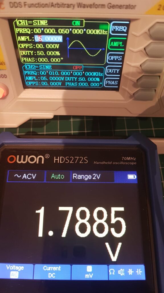
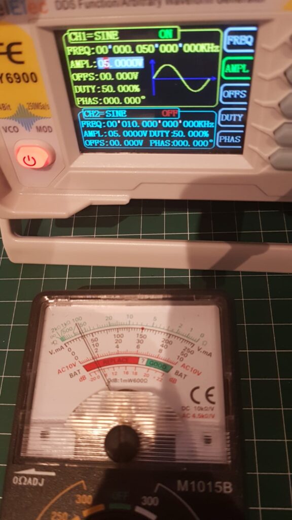
In the above photograph, the red line shows an Output Channel (CH1) on the Function Generator connected to Input Channel (CH1) of the Oscilloscope. That’s how the Oscilloscope is able to see what’s coming from the Function Generator, and shows it to us on a graph, along with many parameters that characterise this AC Voltage.
The magenta line shows that CH1 is generating a SINE wave (upper left corner), and also shows a sample of how the curve is expected to look like. On the Oscilloscope, we indeed see a wave like graph – this type of graph is also produced when we plot a Sine function (a trigonometric function) on a graph. Therefore, this type of graph is also called a Sine Wave graph. Electricity supplied by mains connection, and generators has AC Voltage, which has the same graph as the one shown in the photograph above. That’s also the reason why we denote AC with ~ symbol.
The green line points to FREQ: 0.05KHz on the Function Generator, which is 0.05×1000 = 50Hz, and it is also shown on the Oscilloscope, a verification that the Function Generator is indeed generating a 50Hz Sine Wave or Sinusoidal Waveform.
The blue line points to AMPL: 5V on Function Generator, which means that we have set an amplitude of 5V, and it is also confirmed by the Oscilloscope as it reads Va=5.000V (Va= Voltage Amplitude).
A Function Generator is able to produce many other waveforms, we have selected Sine Wave. It also allows us to set the Frequency and Amplitude of the Sine Wave, along with some other parameters.
We just measured several parameters of an AC Voltage with an Oscilloscope. An Oscilloscope is a kind of very advanced multimeter.
What we know about this particular AC Voltage is as below:
Frequency: 50Hz
Amplitude: 5V
So how much AC Voltage is it? It’s not 5V AC.
Let’s measure it with a multimeter to find out. Actually with several multimeters to demonstrate that they aren’t as good at measuring AC Voltage, compared to their capabilities of measuring DC Voltages.
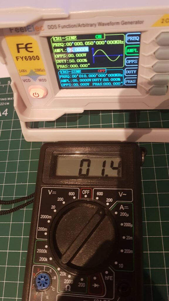
Middlesex University Teaching Resources: 1.4V AC
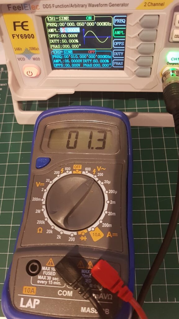
LAP: 1.3V AC
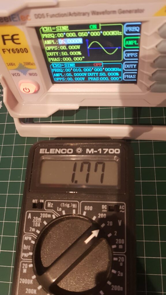
Elenco: 1.77V AC
OWON: 1.7885V AC
Anaogue: 1.45V AC
These all are telling different values… so which one is correct?!
From looking at the graph on Oscilloscope, we know that it’s a fairly good Sine Wave. There is a formula for calculating AC Voltage available from a sinusoidal waveform, which is:
AC Voltage = VMax / 21/2
The amplitude for the sinusoidal waveform was 5V, the minimum voltage was -2.5V at the bottom of the trough, and maximum voltage was 2.5V at the top of the peak. So,
VMax = 2.5V and
AC Voltage = 2.5 / 21/2 = 1.77V AC
Elenco gave the 1.77V AC reading, making it most accurate at measuring AC Voltages, and OWON as second best, and LAP gave the worst reading at 1.3V AC, followed by Middlesex University at second worst.
If AC Voltage is 220V, can you calculate VMAX and Amplitude?
We are going to skip measurement of mains AC Voltage for now because of two reasons:
- You need to learn a lot more about how to protect yourself from electric shock first
- Measuring mains AC Voltage will not help you in learning electronics at this stage
Mains AC Voltage is dangerous and can kill you
What can Voltage do?
So we can measure Voltage with a Voltmeter, but what use is it?
Basically, the physical world is characterised by inequality and disturbance, but it is continuously trying to achieve a balance and equality in everything. For example, water does not like being at different levels, it will try to achieve same level everywhere if it can find a way. To do that, it flows from higher level to lower level. This flow of water is called a current, and we can measure different characteristics of the current. Things don’t like to be at different temperatures either, and heat flows from hotter things to colder things. Similarly, things don’t like being at different voltages, and whenever possible, electricity flows to achieve same voltage. This flow of electricity is also called Current.
Just like we can make flowing water do work for us, like running a watermill, or a turbine. In the same way, we can make flowing electricity do work for us, like running a fan, lighting up a bulb, or powering up any of our electrical devices.
Next Topic: Current
4,533 total views, 5 views today
Excellently explained. A very good read for the beginners. Keep writing ?
Wonderful! A beginner can follow this without a problem. I want to read more!
Mashaallah
JazakAllah
This is amazing. You are doing marvellous work. I must share this with the kids and even seniors. This is very informative for beginners, age is not a limit for learning.