AutoCAD VBA Version
Help>About
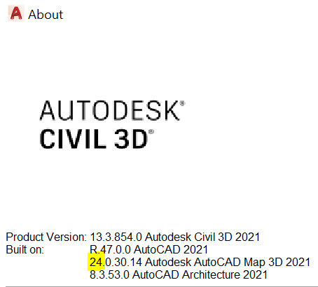
Example: Set color = AcadApplication.GetInterfaceObject(“AutoCAD.AcCmColor.24“)
Trim not working
EDGEMODE = 1
TRIMMODE = 1
These are the usual solutions when trim is not working with extension of the lines. Other issues that I have encountered are lines not being on the same plane, i.e. they are on different elevations, or some lines are 3DPOLYLINEs.
If the lines being on different elevations is unintentional, just select all the lines, and then in properties, set elevation to 0 for all.
For turning 3DPOLYLINEs to 2DPOLYLINEs, easiest way is to download a lisp script. I found one that does just that. Search online for pline-3d-2d.lsp, I found it here:
forums.autodesk.com/t5/autocad-forum/3d-polyline-to-2d-polyline/m-p/2561187#M278793
New trip works without asking a trim edge to select. To disable this new mode:
TRIMEXTENDMODE=0
Hatch problems
AutoCAD has had hatching issues since forever and hasn’t been able to fix them so far. It’s always a good idea to save the drawing before attempting a hatch, as sometimes AutoCAD just crashes when you try to hatch. Some common hatch issues and their workarounds are described below.
Hatch not working
Hatch can have a lot issues, sometimes there are very small gaps in what seems to be a closed boundary.
The worse issue I have come across, which took a while to figure out is if you have multiple coincident points, which are adjacent in the vertex array of a polyline, then AutoCAD refuses to work.
Hatch becoming solid instead of showing the selected pattern
Apart from the usual Scale issue of a hatch, sometimes the hatch just doesn’t accept any pattern and appears solid, whatever you do.
In some drawings, it worked by changing the units from Unitless to mm or m – which obviously is a bug, but in other cases I did not find the reason or a workaround to do a new hatch.
In some cases, Match Properties works from an existing hatch on to a solid hatch, but not always. If Match Properties also doesn’t work then copying an existing hatch and then grip editing it to the boundary works.
Hatch not changing angle, and Match Properties not working
I’ve encountered this with custom hatches which are not installed on the machine. Angle can’t be changed, but the hatch can be Rotated to the desired angle. Then you have to edit the boundary with grips.
Match Properties also doesn’t work for the custom hatches which aren’t installed on the machine, however existing hatches can be copied and then edited with grips to match a new boundary. Easier to copy the hatch from the key/legend as it usually only has 4 nodes/corners.
Custom Hatch patterns not working
If you write your own custom hatch patterns, errors in definition can throw up errors, show distorted patterns, or not show any patterns at all are usually because of syntax or logical errors in the definitions.
Matching Hatch scale in Model Space and Paper Space
Don’t copy paste from Model Space to Paper Space or vice versa. Change space (CHSPACE) through a viewport for automatic translation scale factor.
Model Space linetype scale not matching in Paper Space
PSLTSCALE
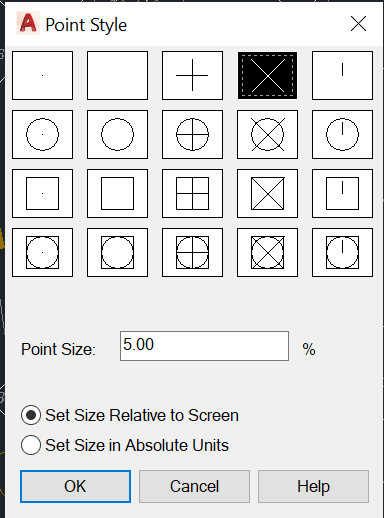
Change Point Style
DDPTYPE
Attributes in a Title Block not showing up
Check ATTSYNC and ATTDISP
Check that attributes are not on a layer that is turned off in any way from displaying or printing
Check that attributes or their layer is not set to a shade of white such as 255,255,255
Check that they are not moved off the sheet by doing a zoom extents
Try REGENALL
I’ve encountered cases where none of the above worked, so if you have other solutions, let me know.
Getting rid of the ribbons and activating the classic menu and toolbar icons
If you have been using AutoCAD for a long time, and have developed speed using toolbars and menus, you will find that ribbons cannot match that efficiency. They may have been developed for touch screens, but a mouse is the most effective interface device for AutoCAD’s GUI. To AutoDesk’s credit, they are still keeping the full range of input methods available, and people can choose what they want (unlike Microsoft! Completely messed up MS Office). Though in many versions you have to set things up step by step rather than just asking AutoCAD to restore the classic interface. Though I have come across a utility on AutoDesk website that did it easily, not sure if it was developed by AutoDesk. There are plenty of online tutorials, so just search for them online.
AutoCAD free alternatives
AutoCAD being very expensive for personal use, it seems to be aimed at companies with sufficient funds. Even though AutoDesk is quite good with providing trial versions and educational versions, I haven’t come across a cheap(er) option for hobbyists and enthusiasts like they do for Fusion 360 now.
To fill that gap, sometimes you can come across clones of AutoCAD. At some point Draghtsight 2D was free from Dassault Systems, but they have started charging now.
These days, you can get NanoCad for free. It’s another AutoCAD clone, and it’s quite good. But it still has small bugs here and there. Maybe they will start charging too when they have ironed out these small issues.
2023: It appears that FreeCAD has progressed a lot and in certain areas can do more than what AutoCAD offers.
AutoCAD for Highways or Traffic Engineering Design
Hatch Patterns
How to Install
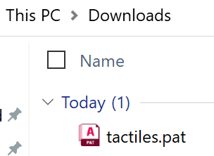
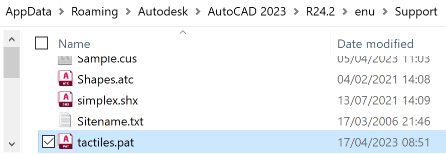
First download a hatch pattern, as an example use the tactiles pattern from the link below:
UK style tactile paving tiles for pedestrian crossings, 400mm x 400mm. Download tactiles.pat from here.
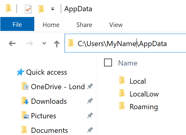
Then open your user account folder on Windows:
C:\Users\MyName\
Here, replace “MyName” with your username on Windows to get to the appropriate folder.
Next you have to go in the “AppData” folder, but this might be hidden. Either select the option to show hidden folders, or type “\AppData\” after your username in the address bar:
Now drill down further into these folders:
Roaming > AutoDesk > AutoCAD 2023 > enu > Support
Here, your AutoCad can be a different version, one shown here is 2023. Next “enu” is for English United States. This can also be different for you, based on what language is installed in your computer. And finally go into the “Support” folder. Now copy the downloaded hatch pattern file to this folder:
How to Use
Hatch patterns have several properties. Some of these are covered here while showing the use case for tactiles hatch.
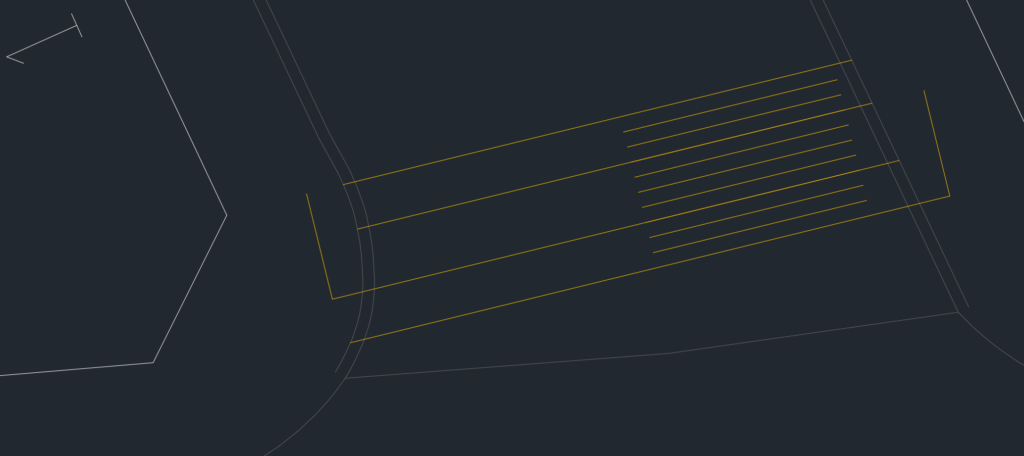
First an outline for the tactiles area is needed. Let’s consider the junction shown below:
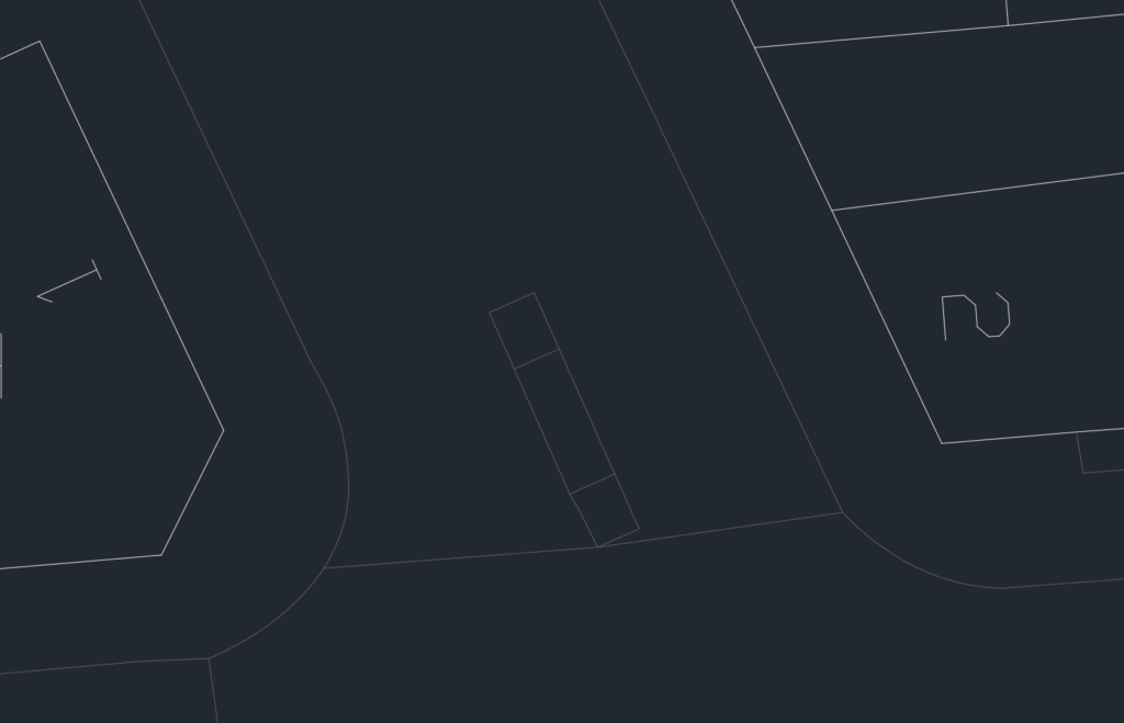
The studs on the tactiles should line up with the crossing path, so that if a blind person was to start walking in line with the studs and follow an imaginary straight line, they should arrive at the tactiles on the opposite side. Any angular deviation will lead them away from the crossing path. This map shows a refuge island in the middle and it’s outline suggests that the crossing path is perpendicular to the footway kerb in the east, and meets a curve on the western side. So the first thing in this case would be to draw a line from the refuge island, perpendicular to the kerb in the east:

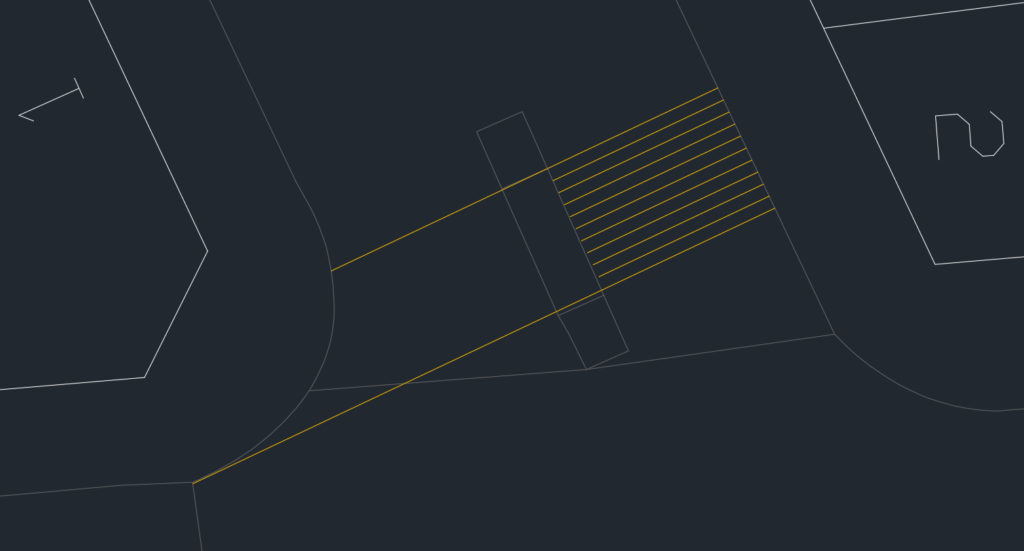
Since the tactiles are 400mm wide, and we don’t use fractional widths, the total crossing width has to be in multiples of 0.4m. We can either measure the width and round it off to nearest multiple of 0.4m, or we can offset the drawing by 0.4m until we cover the full width, as below:
This gives is a width of 4m. Next, we can extend the outer lines to the kerbs on the other side:
This randomly selected location, and the existing refuge island is producing a very odd and unreasonable alignment of the tactiles. Let’s check how on Google Earth how it was implemented in reality!
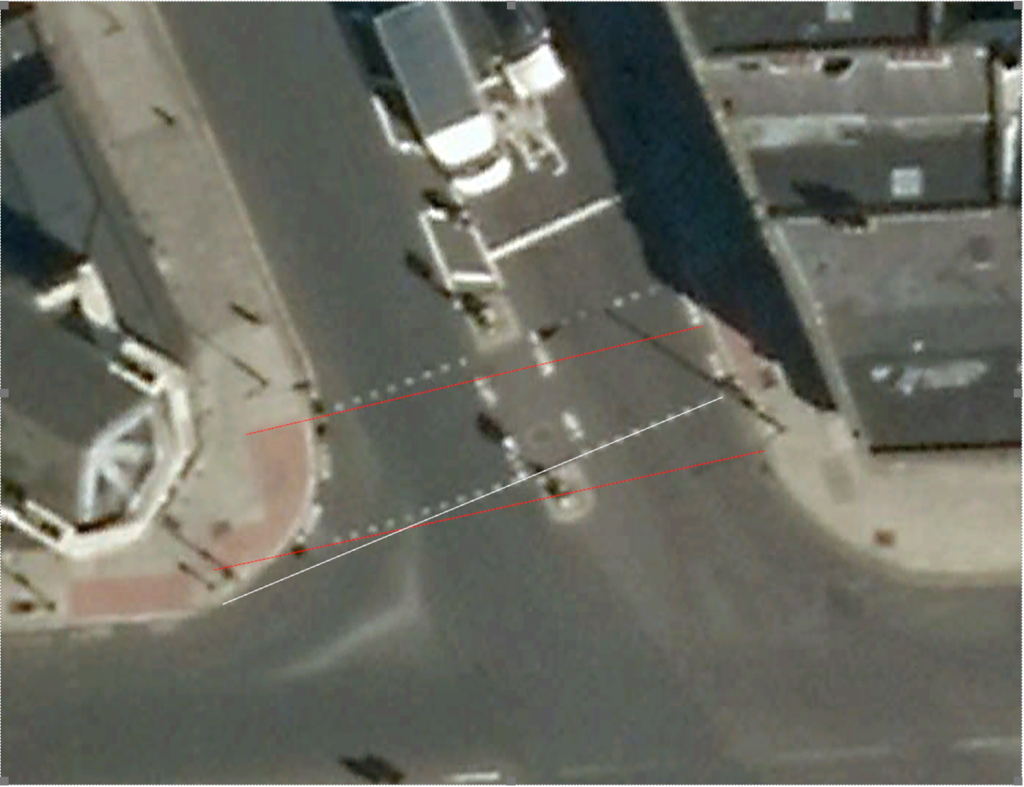
This is a really bad design on multiple levels. The satellite image above is from 2013 (this crossing was like this at least since 2003). It shows that the studs are not in a straight line all the way from one set of tactiles to the other, they change direction in the middle, as shown by the while line. Then the tactiles aren’t aligned to each other. The aren’t even aligned to the refuge island, or the studs. It’s a twisted crossing. If a blind person started from the southern end of the tactiles on the western side of the crossing, they would hit the kerbs of the refuge island rather than reaching the tactiles on the other side of the crossing. This is shown by the red lines, how the tactiles are misaligned.
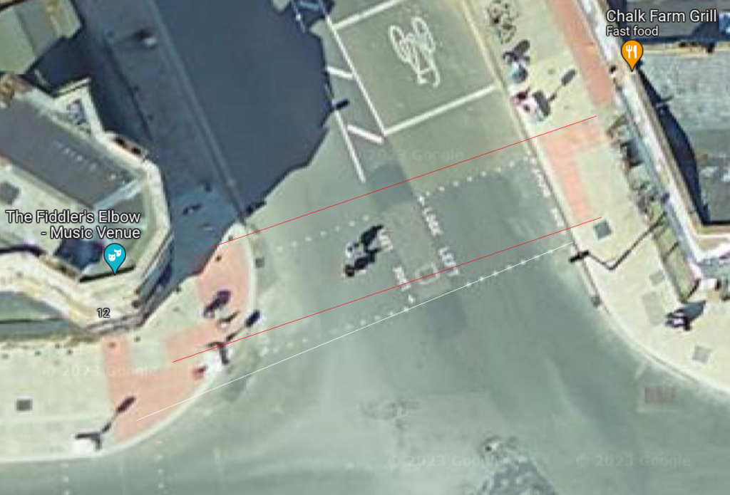
Latest satellite image shows that the footway has been widened, the tactiles seem better aligned to each other, the refuge island has been removed, but the old studs are still present and misaligned.
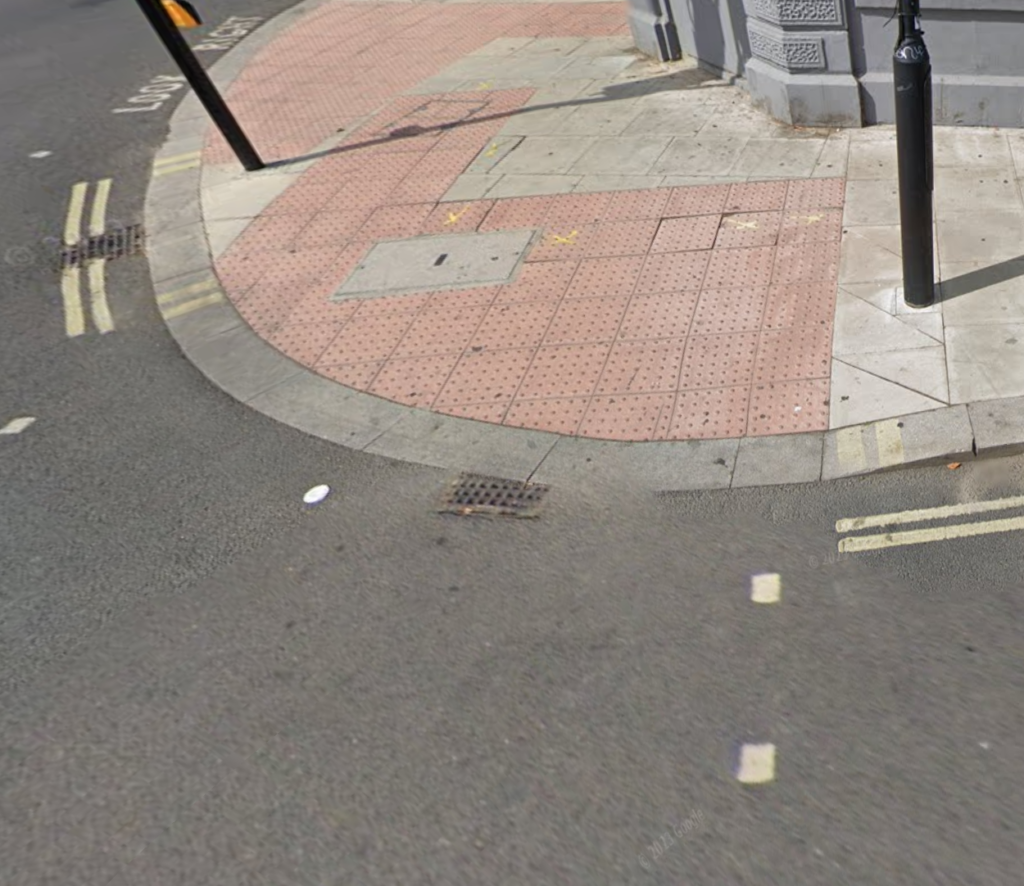
The latest Google Streetview imagery shows a bit misaligned studs, but this could be a panoramic stitching artifact. Perhaps they are aligned better in reality. But the double blips on the left shouldn’t be in front of the tactiles. The depth from the kerb is also excessive. A utility cover hasn’t been replaced by a recessed tray cover, however this could be because of a critical utility that must remain easy to identify in case of emergency, like fire hydrants, gas mains, etc.
In order to achieve a better design, we can remove the island (and rebuild to match the crossing if needed), and reorient the tactiles as below:

Next, we add the kerb width, 0.3m for this location:
Minimum tactiles depth from the kerb needs to be two tactiles or 0.8m. And a 3 tactiles wide (1.2m) strip goes towards the back of footway. We can make this 1.2m offset on both sides as below:

We can now lengthen the lines by 0.8m (using the LENGTHEN command) and drop perpendiculars on them as below:
Now we can just extend and trip the lines to achieve the L shape for tactiles at a controlled crossing as below:
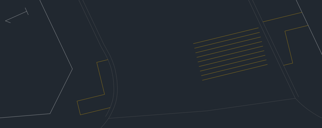
Now delete any construction lines and complete closed polyline outlines for the tactiles as below:

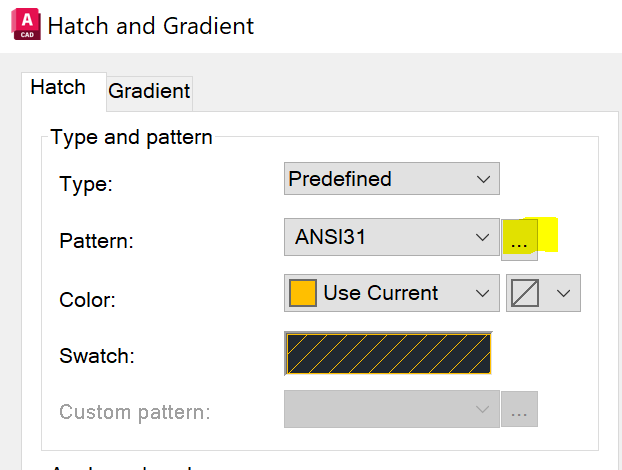
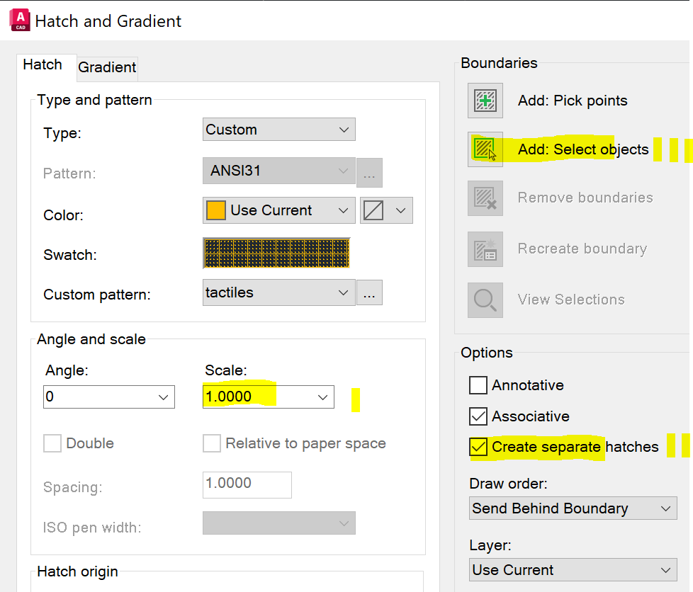
Start the hatch command and then click on the ellipsis as shown below:
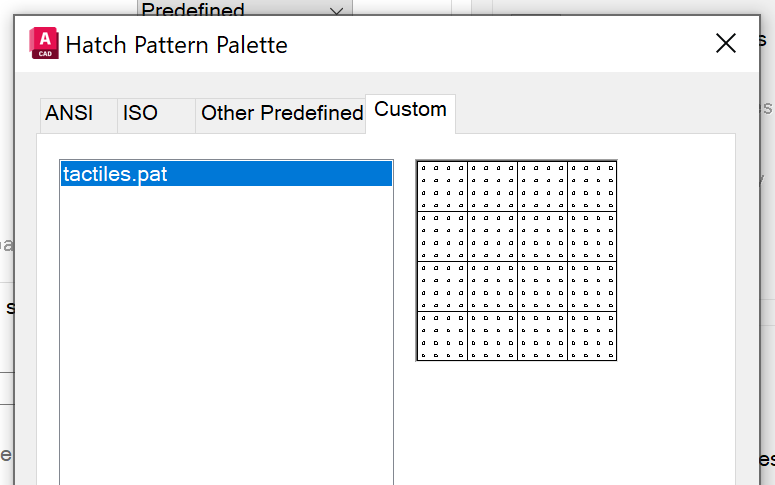
Click on the “Custom” tab and select the tactiles hatch pattern:
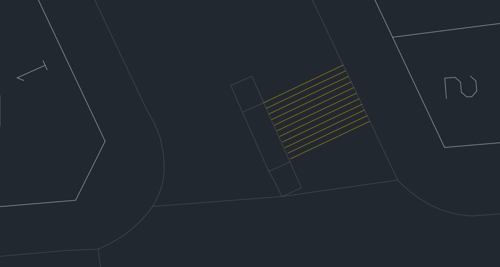
Ensure Scale is set to 1, check “Create separate hatches” to hatch both sides in one go, and then add the outlines created earlier with “Add: Select objects”:
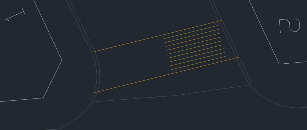
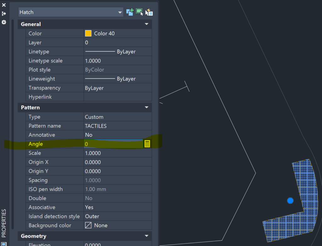
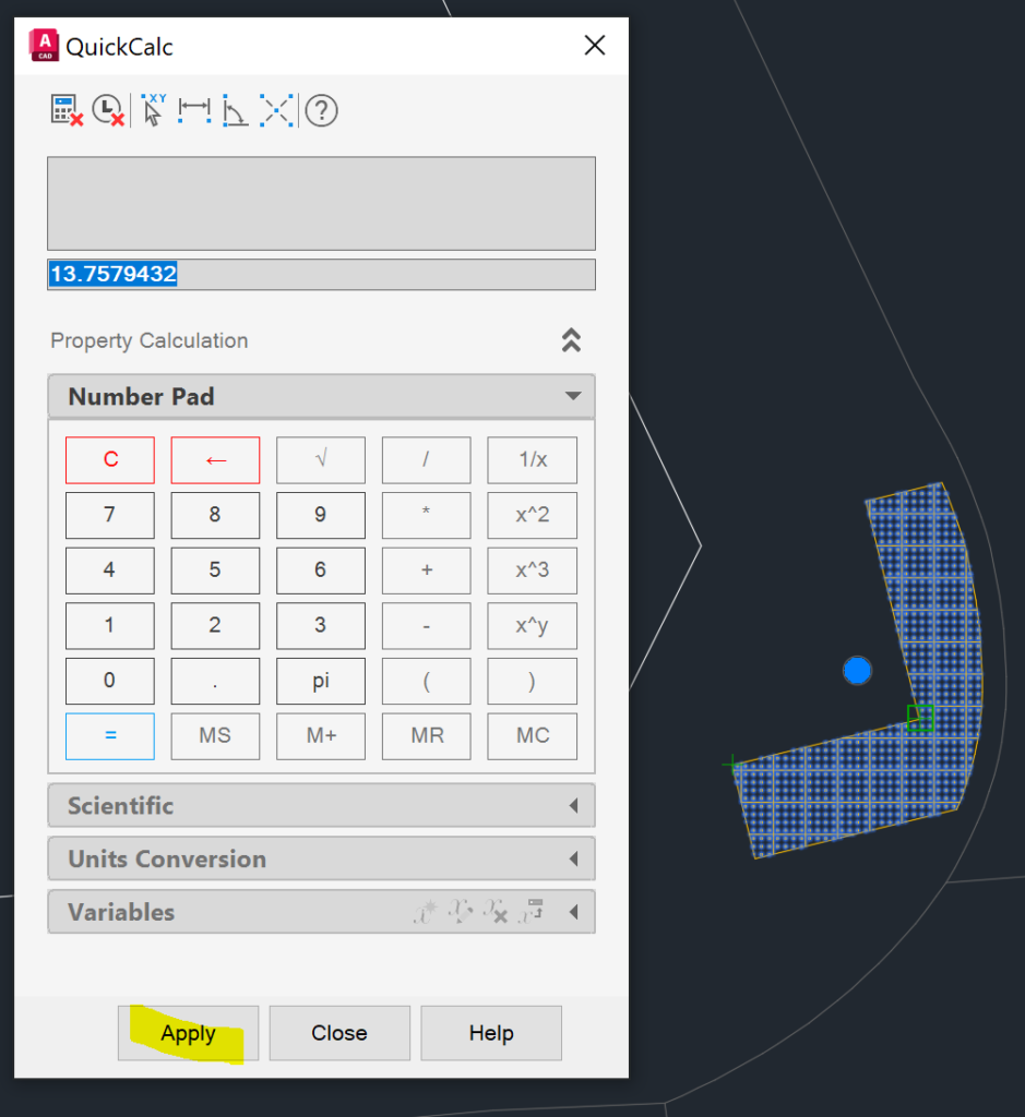
Select the two outlines and apply the hatch, it should look as below. Then angle of the hatch doesn’t match the tactile alignment. To match that, change the angle. With a hatch selected, go to the properties, and select the the calculator icon next to the Angle property:
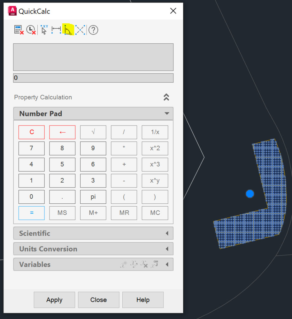
Click on the angle measurement icon
Select any two points on that you want to align the hatch pattern with:
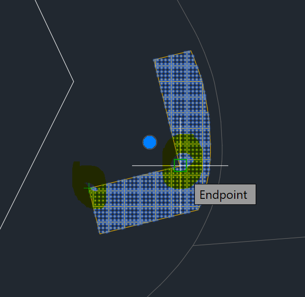
This will measure the angle very precisely. Click on Apply:
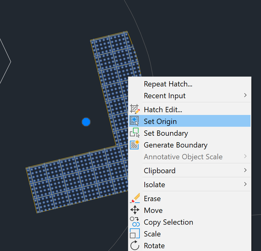
At this point, the angle will be aligned perfectly, but it is quite likely that the tactiles won’t start from the edge. To fix that, right click on the hatch pattern and then click on “Set Origin”, and then click on a corner from where you want to start the tiling pattern:
One set of tactiles is perfectly set. Now use Match Properties command to fix the hatch angle on the other side too. And finally use Set Origin on it as well:
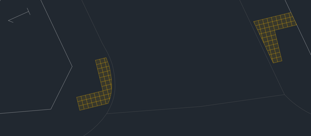
This is a better option than using blocks as they don’t work on the irregular edge, you have to explode and then manually adjust them. It’s better than using lines to show the tiles as well because in case of changes/adjustments, you have to adjust several lines one by one. The hatch can be adjusted much easier with grip editing, or simply rehatching.
Extracting coordinate data for setting out
You can download the file with block definition used below from here https://haibat.com/ipa/SettingoutPoints.dwg
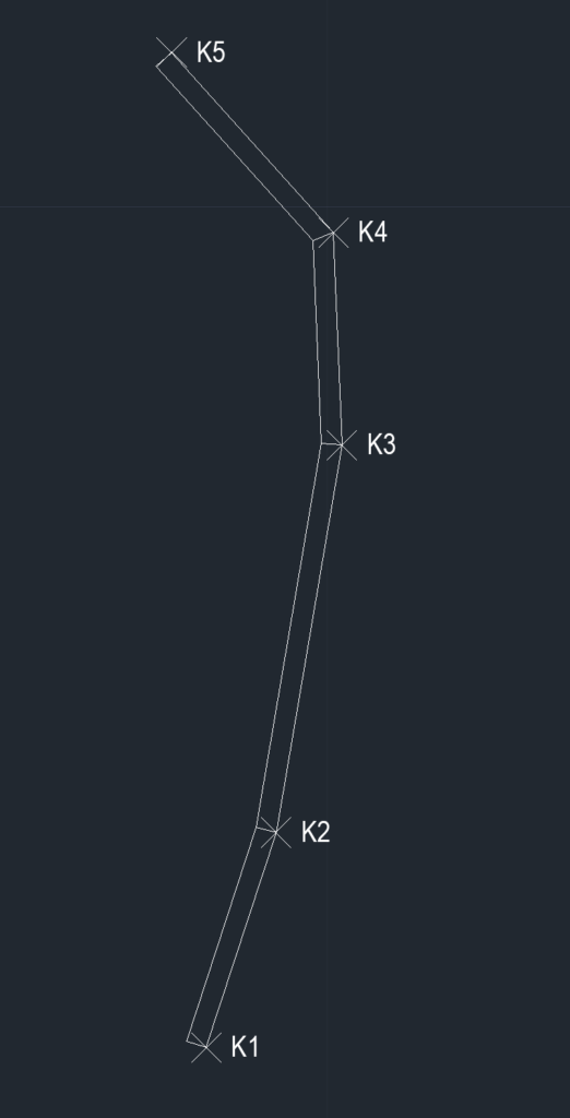
Copy the “setout” block to your drawing, and insert it at all the points you want to extract.
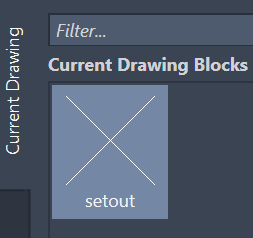
Give each block a different name by double clicking on its name, so that it can be identified:
To begin data extraction, type EATTEXT and press enter:
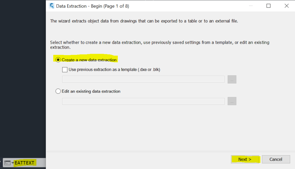
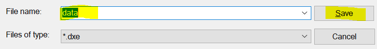
Select “Create a a new data extraction” and click Next. Then type a file name of your choice and click Save:
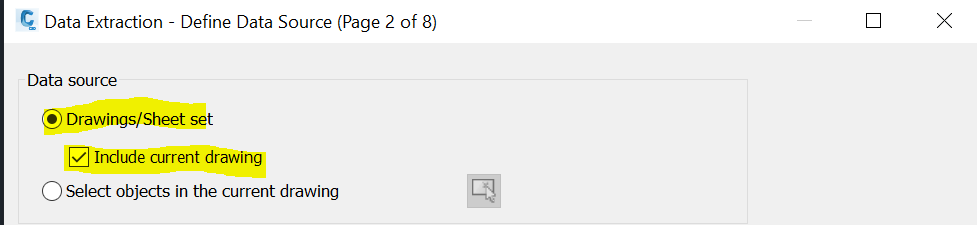
Then tick “Include current drawing” if not already ticked, and click “Next”
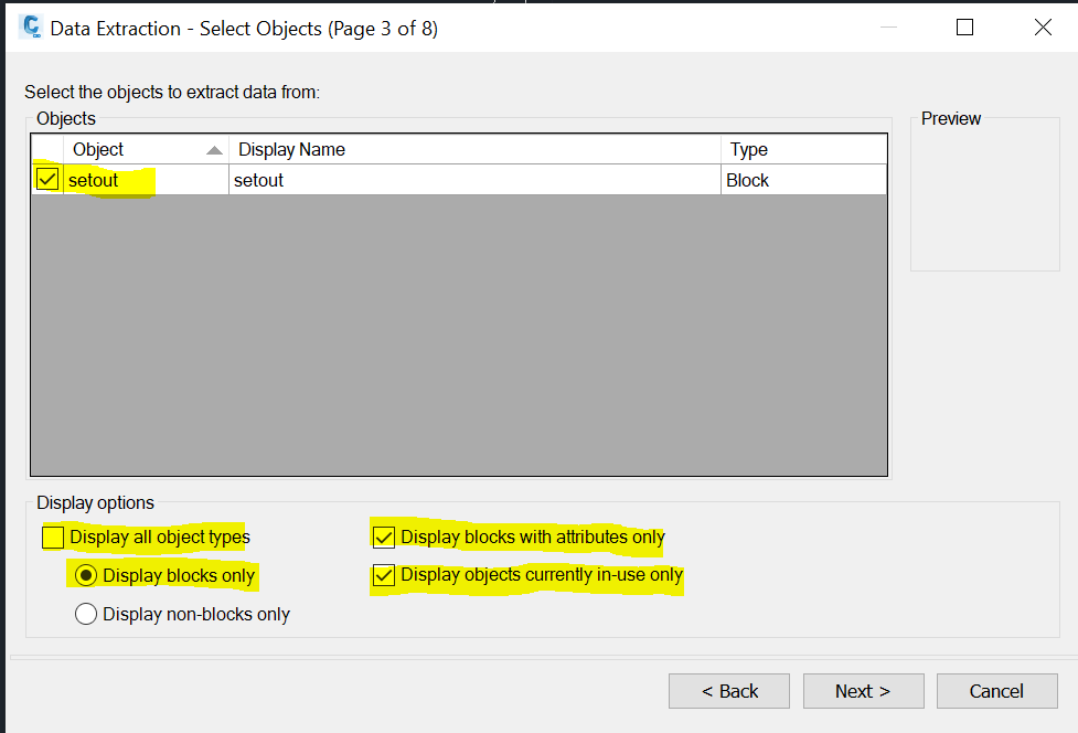
Select “setout” block object, untick any other that are present. In case of many objects on the list, use the below “Display options” to shorten the list
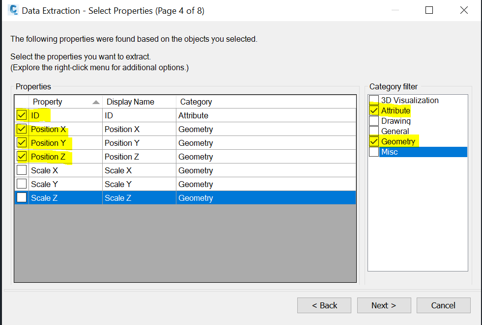
Select properties to extract as below:
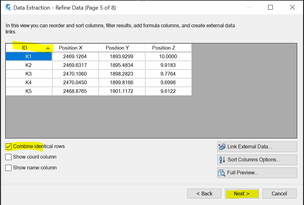
Unselect count and name column options, sort by ID and click next:
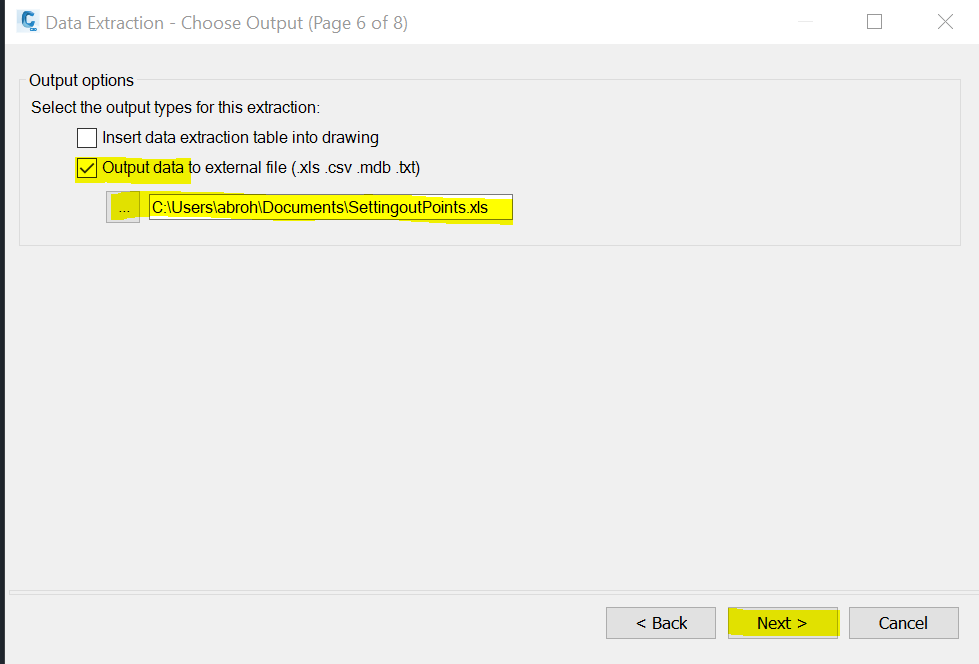
Select “Output data to external file” option, if you want to export to an Excel or other data file. You can insert the table directly in the drawing, but you will get better formatting options in Excel.
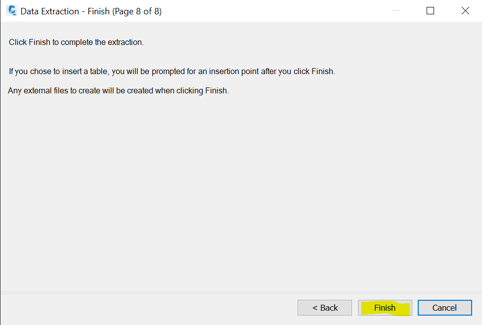
Click “Finish” and then find the Excel file from where you saved it:
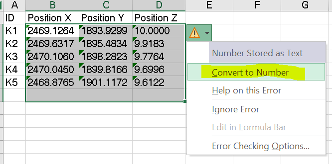
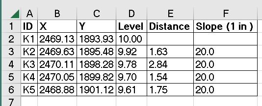
Open the data file. You may have to convert the values to Numbers as below:
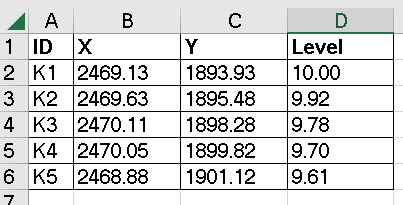
Next format the numbers to 2 decimal places, rename the columns as appropriate, and format the table.
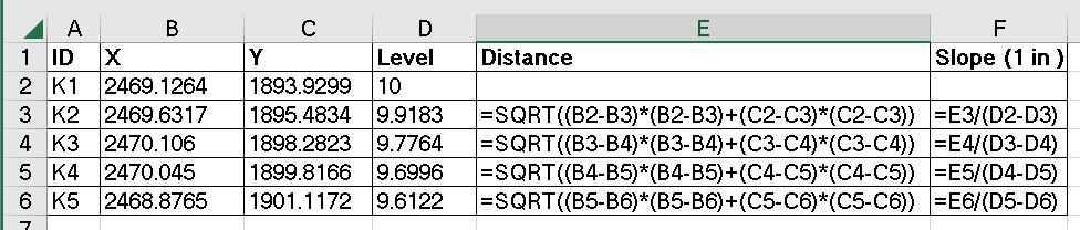
You can also calculate slopes between the adjacent points as below:
3,238 total views, 2 views today