I²C (I Squared C), also referred as I2C and IIC (Inter-Integrated Circuit) is a serial bus communication protocol. This is widely used in making ICs communicate with each other on the same circuit board, or from board to board in multi-board systems.
The communication happens over two lines, one for data SDA (Serial Data) and one for clock SCL (Serial Clock). SCL is sometimes written as SCK on some boards, like the Digispark I have. SDA and SCL remained pulled high when idle, transmission is achieved by ICs sinking the current, pulling the lines low, which can be detected by other ICs on the bus.
Digispark is a 3.3v device, while the Uno works on 5v, making them incompatible to communicated directly. Even though people often connect them directly, and I haven’t come across any reports of the a Digispark being damaged by doing so, it is still not a good practice. The risks are either getting the lower voltage device being damaged by higher voltage, or the voltage not being able to pull high enough to register is high on the higher voltage device.
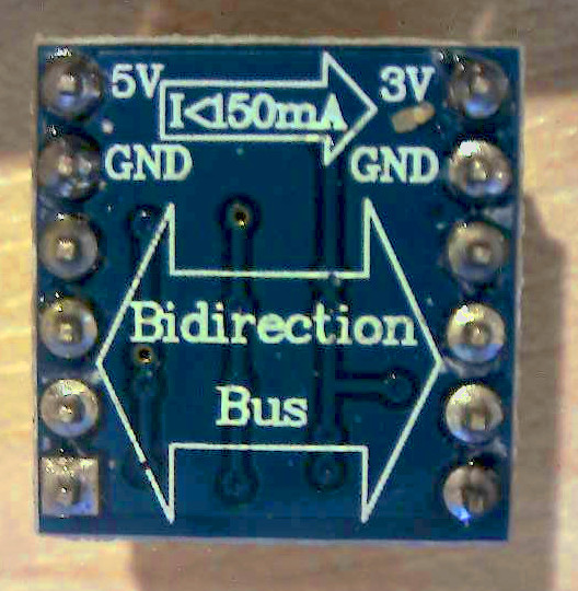
Good practice would be to translate the voltage levels, which can be achieved in several ways as described here. I’ve used a level shifter module as shown in the diagram below.

In the above diagram, the Uno will act as a master device and the Digispark as a slave device. Digispark is on the 3.3v side of the I2C bus, and Uno on 5V side. The Digispark is also controlling the LEDs on the breadboard.
Following programs demonstrate how I2C can be used in this configuration.
For I2C implementation on Digispark, you will need the TinyWire library, which you can download from here. You can download the zip file and unzip it in the libraries folder.
Testing Digispark
The first program I wrote was to test that all four LEDs are working with the Digispark.
|
1 2 3 4 5 6 7 8 9 10 11 12 13 14 15 16 17 18 19 20 21 22 23 24 25 26 |
//Digispark LED test program void setup() { pinMode(1,OUTPUT); pinMode(3,OUTPUT); pinMode(4,OUTPUT); pinMode(5,OUTPUT); } void loop() { digitalWrite(1,1); delay(50); digitalWrite(1,0); digitalWrite(3,1); delay(50); digitalWrite(3,0); digitalWrite(4,1); delay(50); digitalWrite(4,0); digitalWrite(5,1); delay(50); digitalWrite(5,0); delay(50); } |
Like me, you may find that the LED on Pin5 is not blinking. What this normally means is that the Digispark is a Chinese clone. On the Chinese clones, RSTDISBL fuse is unprogrammed. This can be programmed as described here to enable digital I/O on Pin5.
I²C Communication
In the following code for the Digispark, a message received on the I²C bus raises an interrupt which calls the processCommand() function attached to it. In the processCommand() function, if the received character happens to be a number between 1 and 4, then the corresponding LED is turned on and current time is noted.
In the loop(), turned on LEDs are turned off after half a second.
|
1 2 3 4 5 6 7 8 9 10 11 12 13 14 15 16 17 18 19 20 21 22 23 24 25 26 27 28 29 30 31 32 33 34 35 36 37 38 39 40 41 42 43 44 45 46 47 48 49 50 51 52 53 54 55 56 57 58 59 60 61 62 63 64 65 66 67 |
//Digispark I2C with 4 outputs v1.0 #include <TinyWire.h> byte selfAddress = 1; unsigned long start1; unsigned long delay1=500; unsigned long start2; unsigned long delay2=500; unsigned long start3; unsigned long delay3=500; unsigned long start4; unsigned long delay4=500; void setup() { pinMode(1,OUTPUT); pinMode(3,OUTPUT); pinMode(4,OUTPUT); pinMode(5,OUTPUT); TinyWire.begin(selfAddress); TinyWire.onReceive(processCommand); } void loop() { if(millis()>(start1+delay1)) digitalWrite(1,0); if(millis()>(start2+delay2)) digitalWrite(3,0); if(millis()>(start3+delay3)) digitalWrite(4,0); if(millis()>(start4+delay4)) digitalWrite(5,0); } void processCommand(int i) { while (TinyWire.available()) { char c = TinyWire.read(); if(c =='1') { digitalWrite(1,1); start1=millis(); } if(c =='2') { digitalWrite(3,1); start2=millis(); } if(c =='3') { digitalWrite(4,1); start3=millis(); } if(c =='4') { digitalWrite(5,1); start4=millis(); } } } |
There is a rare possibility that the processCommand() is invoked close to the last half a second before the millis() overflows (in about 50 days from power-on) and starts from zero again, in which case that LED can remain on for a very long time. For an automated system that is expected to remain on for longer than 50 days, such issues should be fixed. For this particular problem, it can be fixed as below:
Preventing millis() overflow issue
The solution is simple, as described here. Modified code is given below:
|
1 2 3 4 5 6 7 8 9 10 11 12 13 14 15 16 17 18 19 20 21 22 23 24 25 26 27 28 29 30 31 32 33 34 35 36 37 38 39 40 41 42 43 44 45 46 47 48 49 50 51 52 53 54 55 56 57 58 59 60 61 62 63 64 65 66 67 68 |
//Digispark I2C with 4 outputs v1.1 // millis() overflow issue fixed #include <TinyWire.h> byte selfAddress = 1; unsigned long start1; unsigned long delay1=500; unsigned long start2; unsigned long delay2=500; unsigned long start3; unsigned long delay3=500; unsigned long start4; unsigned long delay4=500; void setup() { pinMode(1,OUTPUT); pinMode(3,OUTPUT); pinMode(4,OUTPUT); pinMode(5,OUTPUT); TinyWire.begin(selfAddress); TinyWire.onReceive(processCommand); } void loop() { if((millis() - start1) > delay1) digitalWrite(1,0); if((millis() - start2) > delay2) digitalWrite(3,0); if((millis() - start3) > delay3) digitalWrite(4,0); if((millis() - start4) > delay4) digitalWrite(5,0); } void processCommand(int i) { while (TinyWire.available()) { char c = TinyWire.read(); if(c =='1') { digitalWrite(1,1); start1=millis(); } if(c =='2') { digitalWrite(3,1); start2=millis(); } if(c =='3') { digitalWrite(4,1); start3=millis(); } if(c =='4') { digitalWrite(5,1); start4=millis(); } } } |
Arduino Uno code
This Uno program listens to the serial port (RS232), and forwards any character received to the Digisark, which we have programmed above.
|
1 2 3 4 5 6 7 8 9 10 11 12 13 14 15 16 17 18 19 20 21 |
//Arduino Uno code for I2C communications with Digispark #include <Wire.h> void setup() { Serial.begin(9600); Wire.begin(2); } void loop() { while (Serial.available()) { char c = Serial.read(); Wire.beginTransmission(1); Wire.write(c); Wire.endTransmission(); } } |
Usage
Open the appropriate COM port monitor in Arduino IDE and select 9600 baud rate. Sending any number from 1 to 4 will turn the corresponding LED on for about half a second. Timing for LEDs is independent of each other. If you send ‘1234’, it will turn on all 4 LEDs for half a second each. Sending ’31’ will turn on the first and third LEDs for half a second.
4,143 total views, 2 views today